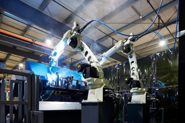
One of the challenges of planning a new welding automation project is visualizing the equipment layout. There are many configuration options from which to choose. What’s highly efficient in one facility might bog down production in another. It all comes down to your goals and the details of your manufacturing process.
Here are some things to keep in mind as you design your welding cell.
Standard vs. Custom
In many cases you have a choice between what is sometimes called commercial-off-the-shelf (COTS), pre-engineered, or custom-built systems. Budgetary and production goals are a big part of this decision.
COTS systems are generally a standard package which includes the structure/work cell frame, robot, gun, safety equipment, and part positioning mechanisms (turntables, trunnions, etc.). You may have a choice between one or two models of some components, but usually options are limited due to the standard size of the frame or other pre-engineered factors. Some systems can be expanded to add an arm or change out equipment in the future.
Custom systems often have a similar look as off-the-shelf systems, or they may even start out as an off-the-shelf structure that your integrator modifies to meet your requirements. This approach maximizes flexibility of the footprint, shape of the weld cell, and the part sizes and operations it can accommodate.
With a custom system, it may even be possible to integrate welding with other tasks that come before and after. Some examples are:
- Adding a second robotic arm with a gripper to load and unload a rack of components
- Connecting conveyors to bring in components from a neighboring CNC machine
- Send them out to a camera inspection station.
A custom system can also be designed with extra space or an expandable structure/frame that can be modified for a larger quantity or different-shaped parts in the future.
Common Configurations
Many welding cells contain either one or two welding stations, as seen in these COTS examples of single and dual layouts:
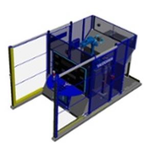
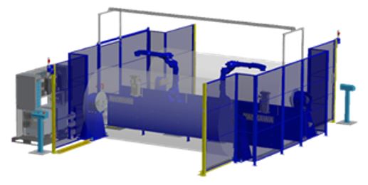
Some configurations also include a dedicated space for the controls and operator. Note that adequate space and guarding for safe operation is built into the design.
In this single arm, custom-built example, components are manually loaded and removed, and a robot does the welding. This system was designed for future expansion to accommodate two welding arms.
Layout Influencers
To get the most benefit from welding automation, you must match the system to the specifics of the job and production volume. For example, will the machine be used to weld a large number of parts with a few welds each? Or, will a single component remain in the machine for an hour (or something in between)? These are some of the factors that influence system layout:
- Part size, shape, and orientation in the machine. These impact the amount of space surrounding the part to avoid damage as well as provide enough space for the robotic arm to move around it.
- Part variety. Robotic welding usually requires that parts be uniform so the robot can be programmed to repeat movements. However, families of similar parts can often be accommodated with the same machine. You’ll need to consider the space needed for changeover, variations in size or shape of components, and what the operator will need access to in order to make the switch.
- Welding details. This includes:
- Arc or spot welding – which can affect arm path differently
- Weld locations and access points/limitations
- Number and complexity of welds and sequencing
- Robot arm reach. This is critical with regard to access points on the workpiece.
- Interaction of the component and robot. How is the part presented to the gun? You’ll need to decide if the arm or the part will be moving, as shown in these examples:
- Operator and robot work zones. Think about workflow and especially where the operator is in relation to the moving arms. Timing is also a factor here: does the job run independently for a period while operator works on a different task? Or is there continual loading and unloading?
- Safety equipment. Proximity of the operator and other workers passing by the cell may require protection from errant sparks, fumes, or moving equipment.
- Cell entry points and robot tool access. Consider access needs for adjustment, changeover, loading or unloading, maintenance, or future expansion.
- Cable and hose routing. Sometimes called the robot’s dresspack, this refers to how cables and hoses are situated: inside or outside the arm. This may depend on rotation and articulated movement required and the volume of welding to be done (i.e. how much use the robot will get and resulting wear on the cables and hoses). Also consider what else is going on inside the cell.
- Inspection equipment/process. Think about when and where inspection takes place in relation to the welding process, and if this is done by a human or additional automation equipment.
No matter what configuration you select, there are many decisions to make along the way. Do you know where you want to end up, but aren’t sure how to get there? Contact us today!