To implement automation in welding effectively and maximize your ROI, you need to approach it as a system, not merely a torch-wielding robotic arm standing in for a human welder. Thinking about the flow of parts into the welding cell, how they’re fixtured and welded, and where they’re transferred next may present opportunities to boost efficiency, save space, or open up production bottlenecks.
If you’ve thought about adding automated welding to your facility, there are many things to consider from equipment and system design to safety to how it will affect your current welder employees. Read on to see if this popular robot application is right for you.
A Snapshot of Automated Welding
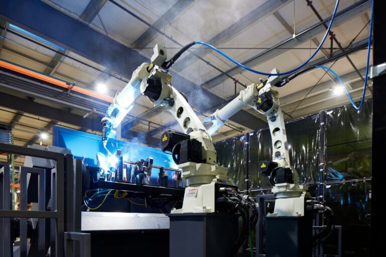
One of the top industrial robot applications is automated welding. Assembly Magazine cites the International Federation of Robotics’ findings that 50 percent of all the world’s robots are used for welding: 33 percent for spot welding, 16 percent for arc welding, and 1 percent for some other type of welding operation.
And we can expect to see it expand in the near future. Between 2018 and 2023 the market for welding automation is projected to grow at a CAGR of 8.91%, especially in the automotive and transportation segments.
It’s been almost 60 years since General Motors first used their UNIMATE industrial robot for spot welding in 1962. What started as a way to protect workers from the most dangerous, undesirable jobs was gaining popularity across the automotive and other industries by the 1980’s. Today’s manufacturers have embraced robotic welding and now many are finding ways to integrate it into larger automated systems to save time, compensate for worker shortages, and improve quality and production.
Most robotic welding falls into three categories: arc welding (generally MIG or TIG), spot welding, and laser welding. Sheet metal is by far the most common material, usually made of either aluminum or mild or stainless steel, but components like nuts, caps, and tubes can be welded by machines too. Applications are almost limitless thanks to the dexterity of multi-axis arms and thoughtful design of fixtures and sensors.
Components in a Robotic Welding System
At first glance it might appear a robotic arm and torch are all that’s needed to automate the welding process. There are actually several components required for optimal performance and, even more important, human safety.
It’s more accurate to view automated welding as a system that includes the entire work cycle: a part enters the cell or work area, it’s positioned with fixtures, the weld is completed, the part is ejected or removed, and then transported out of the work area.
(Click to Expand)
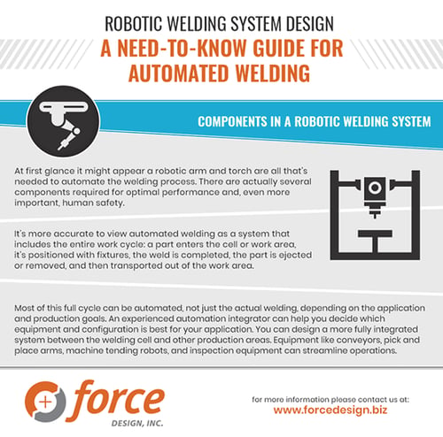
Most of this full cycle can be automated, not just the actual welding, depending on the application and production goals. An experienced automation integrator can help you decide which equipment and configuration is best for your application.
- Welding machine power supply
- Generates the power to create heat for welding
- Many options depending on type of welding and requirements of application
- Cables and supply lines for shielding gases
- Robotic arm
- Multi-axis arm or a linear (e.g. Cartesian or gantry) movement style
- Reach and payload affect the size of items it can weld (i.e. the distance it can travel and weight it can support over that distance),
- Rotation of “joints” adds to flexibility and range of motion; although, limiting factors like part geometry, fixturing, and workpiece position must be taken into account
- Torch
- Bulk electrode wire supply holder and wire feeder for MIG and some TIG arc welding
- Electrodes for resistance spot welding
- Laser for laser welding
- Peripheral equipment for efficient operation such as a wire cutter to trim excess wire, a nozzle cleaning station/reamer, a torch changing station, coatings and covers to protect cables, tools, and parts from excess spatter
- Welding fixtures
- Position and hold parts in place or rotate them for better access
- Large parts may require servo-controlled turntables or gantries
- Design must make it quick and easy to discharge parts, especially if part handling is automated
- The ability to change out fixturing adds flexibility to accommodate part families or entirely different parts. This can be done manually or with automated movements.
- Position and hold parts in place or rotate them for better access
- Sensors
- Options include collision sensing to avoid contact with the torch or other hazardous equipment, seam finding sensors to ensure weld quality and placement, tool center point (TCP) sensors for proper weld placement, sensors and vision cameras to verify clamp and part position
- Safety equipment
- Pressure-sensitive safety mats and personal protection equipment
- Interlocking switches to prevent the machine from working or starting a new cycle unless closed
- Guard locking to prevent a safety guard from being opened or removed
- Sensors, infrared beams, rollup safety doors, and light curtains
- Electronic controls and human-machine interfaces (HMI)
- The HMI can be simple or complex, depending on the application. Examples include a single button or bank of on/off switches or a multi-screen computer app that controls all aspects of the work (e.g. positioning the part, monitoring sensors, part discharge and conveyance to the next station).
- It’s critical to consider levels of access for the different people working with the equipment. For example, which features should be adjustable by the operator and which should be restricted to programmers and/or maintenance technicians?
- Teach pendants allow for on-the-fly adjustments and flexibility in manufacturing. In some applications, handheld devices allow operators to easily program the robot’s movements and store them as a program to run. Other applications, especially those running at high speeds or with short cycle times, require more programming experience.
In addition to these components of a robotic welding system, you can design a more fully integrated system between the welding cell and other production areas. Equipment like conveyors, pick and place arms, machine tending robots, and inspection equipment can streamline operations.
Pre-engineered or Custom? Options for Robotic Welding Systems
There’s more than one way to automate your welding applications. One of the first decisions to make is between Commercial Off the Shelf (COTS) or custom system.
COTS equipment is sometimes called “pre-engineered” because components are sold as a package deal, usually a robot, torch, welding power source, and safety guards. These systems are generally designed as stand-alone, one-size-fits-most cells, generally with few required changes to layout or processes up- or downstream. Some vendors offer a choice of power source or other equipment to customize the cell, and additional accessories or peripherals like sensors or nozzle cleaning tools/reamers may or may not be included as part of the package.
Even a basic system won’t be ready to run right “out of the box” without some amount of configuration and set up time. Especially if your facility is new to automation or robotics, troubleshooting and optimizing workflow may present a challenge, so it’s critical to verify what support and training is included with the cell.
For example, you will probably need fixturing to hold the pieces to be welded in place. The COTS equipment vendor may be able to supply fixtures, but an automation integrator can also design custom fixtures. Integrators can also set up the cell, program the robots, and work with the welder machine to achieve your desired weld quality and specifications.
While they may be cost-effective up front, because they sometimes come with a limited selection of components, pre-engineered cells may not be suited to complex welding tasks or fit seamlessly into a production line. It’s important to consider if a COTS cell will fit in with your existing processes up- and downstream or if it will disrupt the workflow or create inefficiencies.
Custom equipment is generally designed and installed by an automation integrator. Because no two manufacturers have the same process, custom systems let you tailor the system to what’s most important in your situation. The first step in working with an integrator is close analysis of your unique requirements and production goals, along with the general flow of your manufacturing facility.
Only then are specific pieces of equipment incorporated into a design. The time and expense are usually higher up front, but the end result is a welding system that does exactly what you need without extras you can’t use. Many custom systems can also be expanded or integrated with other workstations or processes as your needs change.
Your facility’s size, production volume, and mix of products affects the COTS vs. custom decision too. Smaller facilities with limited space and budget for large, dedicated systems might do better with a compact custom welding system designed to nestle between other work cells.
Larger operations or those with a low-mix and high volume may find that a pre-engineered welding station meets all of their needs easily. Or, to make a high-mix, low-volume operation more efficient, an integrator may bring together single components to coordinate material handling, communications between devices, fixturing, and the actual welding machine.
Integrating Automated Welding with Other Manufacturing Processes
Are you better off with a stand-alone welding machine or incorporating more than one type of machine to manage the flow of components in addition to welding? There is no single right solution for everyone: it depends on part volume, complexity of welds, and resources available (including money, time you have to make the change, and worker availability and skill).
Automation doesn’t have to be all-or-nothing. For example, a manufacturer can have “islands of automation” for some areas such as cutting, welding, inspection, while assembly, machine tending, and material handling remain manual.
Integrated systems often use computer software and connected devices to coordinate components. One powerful tool is programmable automation controllers (PACs), which synchronize equipment with a human-machine interface (HMI) and teach pendant, gather data about speed and motion, and even make adjustments to operations based on data from other equipment it’s connected to.
Examples of integrated welding systems include:
- An automated welding cell that utilizes a MIG robot, nut welder, and material handling robot. It is designed to accommodate 53 different model numbers of welded components and can run for one hour unattended. It also features conveyors, automatic changeover capability (in which fixturing automatically adjusts when a part’s barcode is scanned), and vision cameras.
- A MIG robot welding cell in an automotive manufacturing facility that welds aluminum bumpers. It is a two-station welding process with an automatic transfer between the two weld stations. An operator loads parts into each station, then removes the completed weldments at the end of each cycle.
- Especially when workpieces are large or work takes place in a small area, the ability to coordinate robots’ movements allows several to perform work in the same space at the same time.
Robots can also coordinate with human operators to perform parts of a larger task. For example, while a human operator loads the next part at the front of the welding cell, a robotic arm with a gripper can remove a finished assembly from the weld fixture through the back, then place it on a conveyor. Automating one task/process can have implications up and downstream.
For example, the great precision of robot welding means there’s less room for the variations in cut angles or seam alignment that a skilled human welder can easily adjust for. Cutting/forming must be held to tight tolerances so that part fit-up is at a level a robot welder can work with.
Another consideration is the increase in throughput that may result due to the high speeds possible with automated welding – you need to be sure operations up- and downstream can accommodate the change and that you have a plan for transferring more parts quickly.
The trained eye of an automation integrator can find ways to make changes while still accomplishing production goals, or even improve for efficiency, safety, worker availability.
Welding Fixture Design
According to Assembly Magazine, inappropriate fixtures contribute to 40 percent of rejected parts, so it’s important to realize that without the right fixturing to hold parts in the right place, the robot can’t make accurate welds.
In other words, because robots precisely repeat the same welds paths every cycle, in order to have repeatable, accurate welding automation, the components to be welded must be held in the same correct position each cycle too. And because robots repeat identical motions at a relatively quick pace, defective parts can pile up quickly.
At minimum fixtures need to accept, position, and hold components and discharge weldments quickly and repeatedly. Fixtures must also be durable and not interfere with electric, gas, or fiber optic lines (i.e. the robot’s “dress package”).
In addition, many manufacturers want to stay flexible with their automation equipment – why spend money on a welding robot that can only be configured for a single part? Part families, sets of similar parts with minor variations, are common in automotive and other types of manufacturing, and are one area in which flexible fixturing allows for greater automation. Built-in fixture changeover to accommodate all the variants of a part, or even entirely different parts, often impacts throughput and ROI.
One of the benefits of automating processes like welding is the opportunity to examine it for ways to change or improve workflow or physical set up. When fixture changeover comes into play, it helps to think of it as one aspect of a larger system. For example, when automatically changing out end-effectors several steps are involved, not just swapping one tool for another.
The tool must be recentered, pins and clamps removed and stored (possibly by another robotic arm), then the new tools must be retrieved and installed. For optimal efficiency in welding automation, designers also need a plan for storage and retrieval of fixtures when not in use. Incorporating multiple arms, conveyors, or even mobile autonomous vehicles to help with changeover tasks can make the process more efficient.
There’s a range of fixturing options from simple to complex, and as with most things, the best option is the one that accomplishes your current production, fits into your budget, and addresses plans for any future expansion. At one end of the spectrum are fixtures installed and removed manually with a wrench or hand crank.
Other options include fully automated, servo- or pneumatic-driven changeover, where the machine automatically swaps out tools based on a barcode or a few taps on a touchscreen HMI. Sensors and vision cameras can also verify alignment of plates and parts, and sensors can locate weld seams or verify positioning.
For example, a car seat adjustment mechanism may come in three of four variants depending on the model it goes into. Automated fixturing and changeover can be designed to scan the barcode on the parts, shift the correct fixturing into position, verify that the right parts are being welded, and then complete the weld.
In some applications, vision-guided fixtureless welding is a cost-effective solution. Advances in multiple arm control allow a group of arms to be programmed to coordinate on a process or task, which reduces dedicated tooling and fixturing.
For example, material handling robots equipped with vision cameras can grip and lift several types of frames, brackets, or parts as they move by on conveyors and position them for a welding robot, serving as the weld fixtures themselves. This flexibility saves time and space usually required for dedicated fixtures and tooling.
Tips for Monitoring and Troubleshooting
Quality problems and weld defects such as hot/cold/crater cracking, fissures, porosity, undercut, incomplete fusion or penetration, and spatter happen with automated welding and need to be identified and fixed. Here are some tips for optimal quality:
- Consider if problems are due to recent changes to the process, consumables, or robot programming.
- Perform routine maintenance and equipment checks to identify problems with consumables (e.g. nozzles, wires), power cable wear and tear, wire feed, excess spatter, off-center alignment of the nozzle or misplaced welds, or gas leaks.
- Be aware of how input quality and consistency affects output quality. For example, input parts prepared with CNC machines may contribute to a higher quality, consistent weld seam than those manufactured with manual processes.
- Incorporate peripheral equipment like switches and sensors to detect the presence and location of parts or seam tracking and centering sensors for correct torch and tool placement.
- Staff robotic welding systems with experienced welders. Familiar with common defects and what can go wrong in welding operations, they can quickly assess weld quality right at the point of production and notice when things need adjustment.
- Provide training on the robot(s) and peripheral equipment to develop operators’ skill and comfort levels with troubleshooting the machine, programming (often hand-guided or with a teach pendant) and the ability to convey complex or recurring issues to the offline programmer/integrator.
- Include training on basic system maintenance such as nozzle cleaning and checking wire feeds, to catch problems quickly and to extend the useful life of the system.
- Most automated welding equipment includes software and connectivity to collect data from the welding machine and any sensors or cameras. This is useful for spotting trends, discovering inefficiencies, and pinpointing sources of defects. Data gathered on voltage, current, wire speed and welding speed, weld length and depth, rate of consumables use can also be analyzed and tracked over time.
A Different Type of Work for Welders
Experts debate how extensively automation replaces human workers, but most agree automation changes the very nature of welding and industrial work.
Robotic welding systems shift the manual work of aligning parts in fixtures, welding seams, and moving weldment from one station to another from a person to a machine. Now the welder’s primary role is maintaining the flow of parts and keeping the machine running, loading and unloading pallets or trays, and overseeing the entire welding system. The work has a broader scope, encompassing multiple, dynamic factors.
Despite this shift, operators still need to understand welding, spot and troubleshoot defects, and apply welding skills even if they’re overseeing a robot and not holding the gun in hand.
Welding automation benefits employers too with:
- reduced personnel costs for skilled trade pay, time off, sick days, and insurance
- boosting efficiency and throughput
- lower spending on consumables like weld wire and shielding gases
- addressing the predicted 400,000 welder shortage by 2024
- enabling older welders to continue working into their 60s due to lower physical demands of automated welding
Prioritizing Safety
Most of the dangers of manual welding persist in automated systems. In addition, robots, conveyors, and automated material handling equipment present additional risks to safety. As more and more companies turn to pre-engineered and custom robotic welding systems, worker safety is always a top priority. There are many ways to ensure and enhance safety, such as:
- Operator safety devices and strategies including arc flash guards, eye protection, laser or light curtains, designing adequate space and barriers/gates around the welding area, and fume extraction/shields, identifying and clearly marking danger zones
- Interlocking switches, which either stop the welding machine or keep the next cycle from starting unless the switch is in the correct position, prevent accidental worker contact with the machine. Examples include gates, doors/covers on equipment, levers, and hinges. They can also prevent part or equipment damage from stray movements or spatter.
- Options include electromechanical guards and hinges as well as non-contact fiber optic switches (especially for areas with high levels of EMI/RFI).
- Interlocking devices must be suited to their environment in terms of “the temperature, humidity, dust/abrasives exposure, chemical exposures, and mechanical shock and vibration exposures in the application.” In welding, exposure to heat and spatter are of particular concern.
- Guard locking, which prevents a safety guard from being opened or removed from a hazardous work area or piece of equipment
- Performing a thorough risk assessment to consider all potential hazards presented by the robotic welding equipment, weld fixtures, and peripherals.
- Consider severity and likelihood of potential injuries and frequency of worker exposure to the risks.
- Even with on-board sensors and emergency shut-off controls, tools and parts can present dangers as well. Examples include increased fume exposure, proximity to other hazards, frequency of entry/exit from the cell, and torch and robot reach.
Learn More from the Experts at Force Design
Automation changes everything. From production volume to consumable use to your facility floor plan to your employees’ job descriptions, it’s hard to overstate how much impact robotic welding has. Is it the right change for you? Contact the Force Design team to learn more.